Model Number: O6V1.0 Question Classification: Functions Settings
Using O6 for "point to multipoint", this function is mainly for the use of more than two bridge equipment to monitor video transmission, engineering video surveillance, remote wireless networking design, user-friendly installation and debugging.
Part 1: Prepare for configuration
Part 2: Configure the computer
Part 3: Log into the admin interface
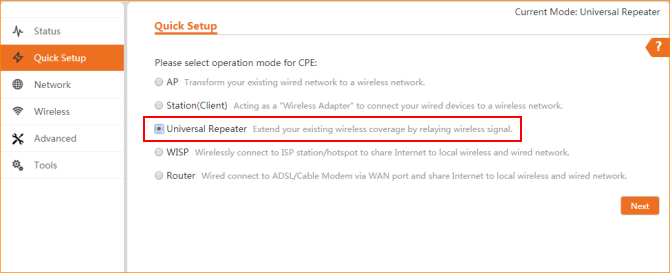
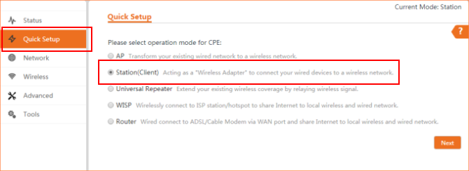
Part 4: Choose the right job mode (with two settings to choose from)
The NVR terminal is set to AP mode, and the camera end is set to station mode (recommended)
OR
The NVR terminal is set into AP mode, and the camera terminal is set as a universal repeater mode
Part 5: Check whether the bridge to success
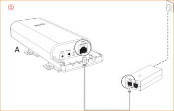
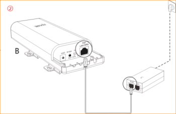
1. The two O6 (B A/ device), two cables, two power supply.
2. Use the power supply, network cable, respectively, to equipment A, equipment B electrify:
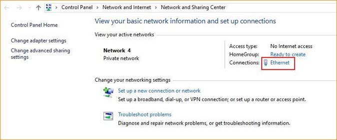
1. First find a small computer network computer icon in the lower right corner of the desktop, right click and select open network and Sharing Center
2. Left click on the Ethernet or local connection.
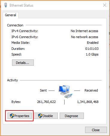
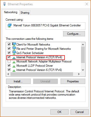
3. Left click Properties
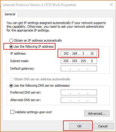
4. The left key selects the Internet Protocol Version (the tcp/ipv4 protocol) -- using the following IP address, the ---ip address, to fill in the 192.168.2.x (one of the values from x=2 to 254) -- the subnet mask, the 255.255.255.0 gateway, does not fill.
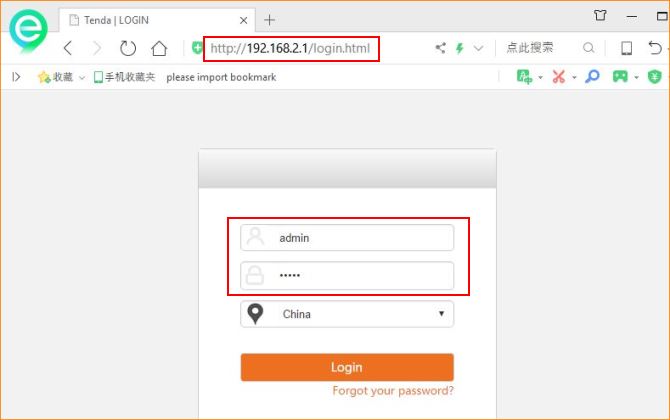
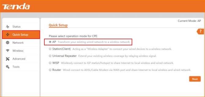
1.open the browser, enter the 192.168.2.1 in the browser address bar, enter the login screen, enter the default login username and password: admin, click the "Login" into the management interface.
the NVR side of the O6 is set to AP mode, the camera side of the O6 set to client mode (recommended)
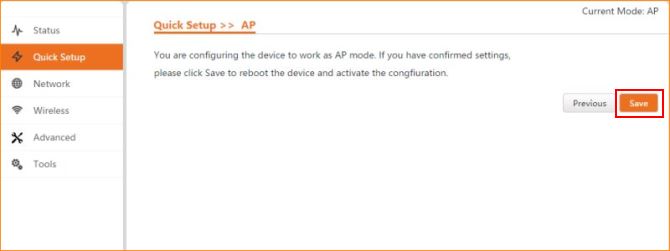
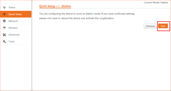
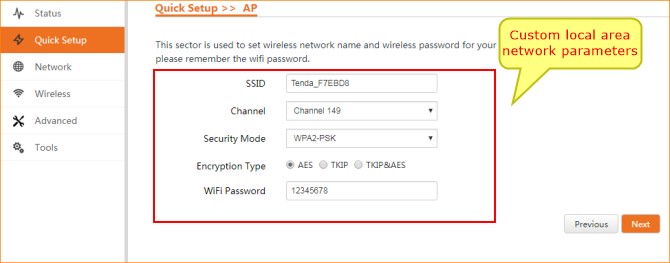
AP mode settings steps as follows:
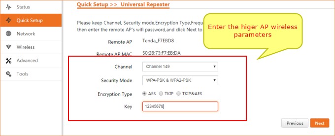
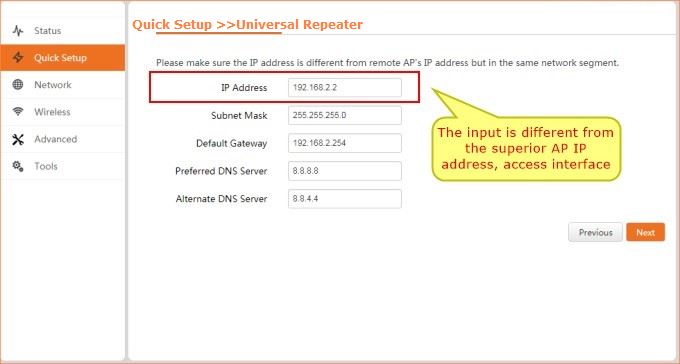
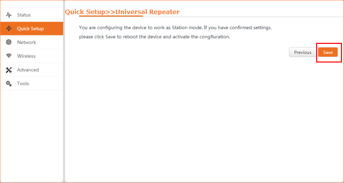
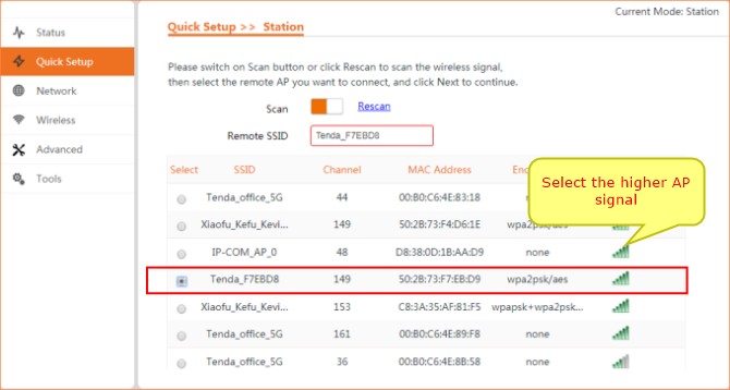
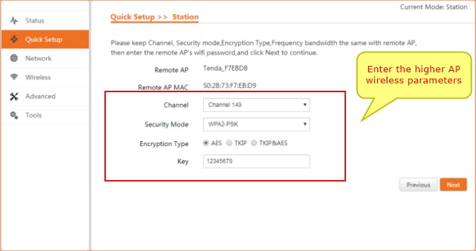
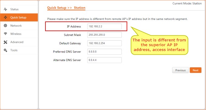
The station mode’s O6 settings are as follows:
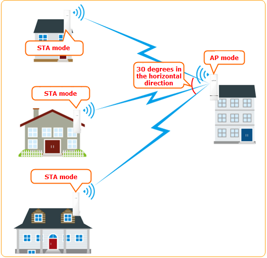
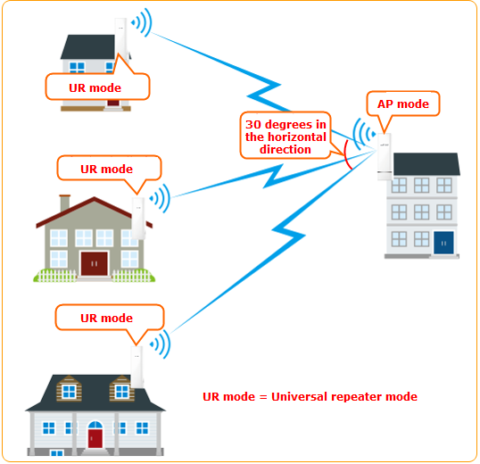
When O6 point to multipoint work, the first networking method, as shown in the following picture: that is, a AP mode O6 corresponding to the O6 of multiple client modes:
Note: AP level angle is only 30 degrees, point to multipoint bridge, as far as possible within the receiver AP signal coverage
2.The second method:
NVR O6 is set to AP mode, the camera terminal O6 set to universal repeater mode
AP mode settings steps as follows:
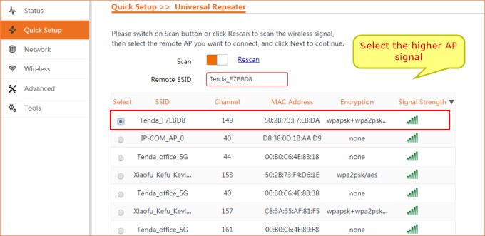
Universal repeater mode O6 is set as follows:
O6 point to multipoint work, second networking modes, as shown below: a AP mode of O6 is corresponding to a plurality of universal relay mode O6
Note: AP level angle is only 30 degrees, point to multipoint bridge, as far as possible within the receiver AP signal coverage
Two methods:
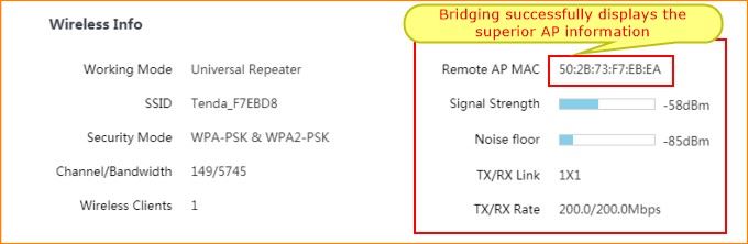
1.you can view the O6 interface to the client:
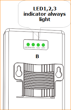
2.O6 can be observed after the panel indicator
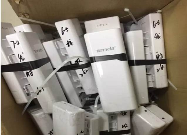
After the success of the bridge, equipment A and B installed on the pole at the corresponding position, which relative to the height
1>By viewing the signal strength indicator (LED1, LED2, LED3) micro adjust the height and direction of the two devices, signal strength indicator lamps are lit for the best position.
2>The LED1, LED2, LED3 respectively different signal strength threshold, LED1 defaults to -90dBm LED2 defaults to -80dBm LED3 default to -70dBm. can be modified in the Web equipment management page by default:
- if the -90dBm< wireless signal strength on the side of the <-80dBm, LED1 light.
- if the -80dBm< wireless signal strength on the side of the <-70dBm, LED1, LED2 light.
- if the -70dBm< on the side of the wireless signal strength, LED1, LED2, LED3 light.
3>Attention: after setting up, use the watercolor pen to mark the corresponding working mode and installation coordinate position, avoid confusion and easy installation
3. outdoor installation, the sender and the receiver equipment should be relative, equipment between buildings and other objects to avoid occlusion, highly consistent as possible, in order to get a better signal.